
#LOOPBACK CABLE DIAGRAM SERIAL#
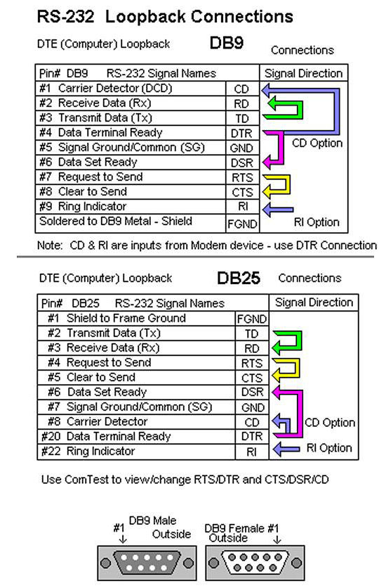
In most circumstances, this path is not required because the use of software flow control is common with most modern serial devices. Likewise, your connected device will use pin 8 (CTS - Clear To Send) to tell the computer when information can be sent.īy connecting pins 7 and 8, we are sending the RTS signal to the CTS pin allowing us to verify that the com port is able to handle hardware flow control. If you dont want to make your own plugs, you can always purchase our serial and parallel loopback. The DB-9 connector as the following 9 pins. In a normal RS-232 connection with hardware flow control checked, the computer will use pin 7 (RTS – Request To Send) to tell the connected device when information can be received. The serial port on IBM compatible PCs conform to the RS232 electrical standard and use a male DB-9 connector. Twist the wires from pins 2 and 8 together. Twist the wires from pins 1 and 7 together. This path handles the flow of information between the computer and device, similar to path 1. Complete these steps to create a loopback plug for a 56K CSU/DSU: Use wire cutters to create a working RJ-45 cable that is 5 inches long with an attached connector.

In most applications, you will only need to connect pins 2 and 3 to test the functionality of a DB-9 serial port. By connecting pin 2 (Rx- Receive Data) to pin 3 (Tx- Transmit data), we are able to verify that the computer is able to send and receive information through a serial connection. This path handles the actual information being transmitted across the serial connection. This handshake, for the most part, just verifies that the modem, or other DTR / DSR enabled device, is turned on and active.īy connecting pins 1, 4, and 6, we are taking the DTR signal and sending it to the DSR pin and the CD pin allowing us to verify that the computer is able to communicate with a modem.Īdditionally, you can connect pin 9 (RI - Ring Indicator) to this path to verify that the computer is able to detect when a call is coming in from the modem. The computer will then use pin 4 (DTR - Data Terminal Ready) and pin 6 (DSR – Data Set Ready) to create a handshake between the computer and modem. The modem will use pin 1 (CD – Carrier Detect) to tell the computer that there is a carrier tone detected or it has made a connection with a second modem. It is important to understand the purpose of each connection for troubleshooting serial connections. You need to use the loopback cable and make a proper connection from the USRP transmitter’s TX to USRP receiver’s RX. Figure 6 and Figure 7 show the loopback cable and the USRP-2922’s front panel. The above tables and wiring diagram outlines the required connections to create a loop back plug. In this type of communication, a loopback cable (SMA (m) to SMA (m) cable) is used as the transmission media.


 0 kommentar(er)
